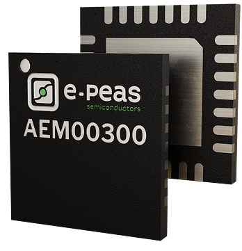
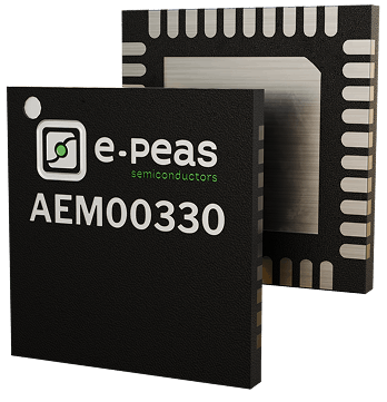
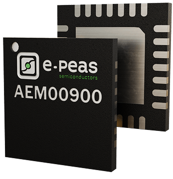
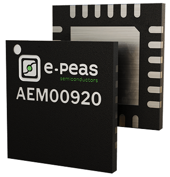
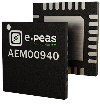
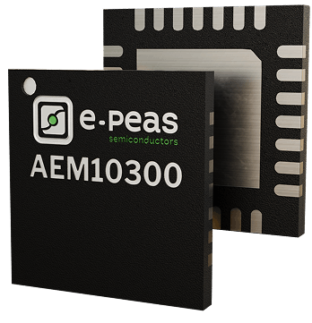
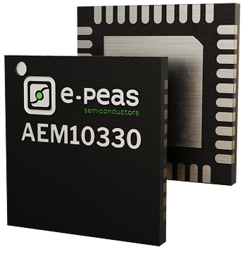
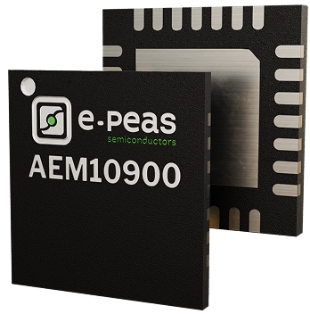
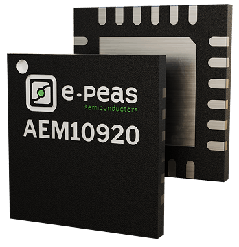
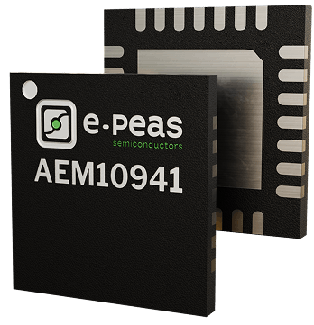
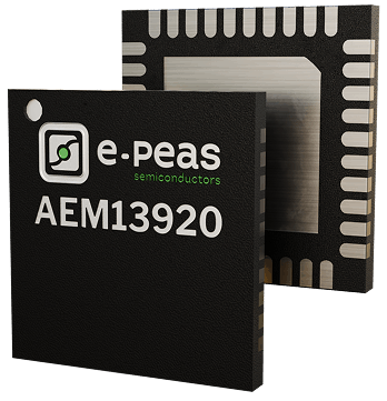
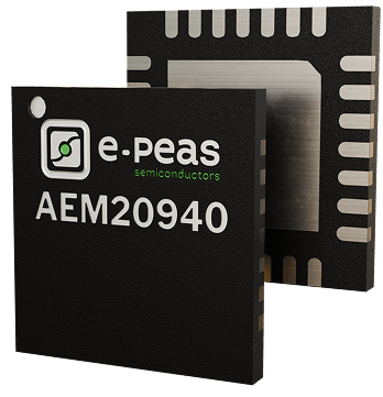
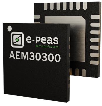
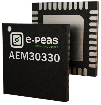
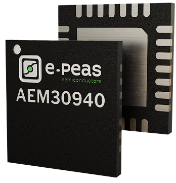
Discover our AEM product family, cutting-edge energy harvesting ICs
Discover the perfect solution to enhance the autonomy of your devices with our extensive range of Ambient Energy Managers (AEMs), designed to harness multiple energy sources and meet diverse configuration needs.
Find the perfect solution for your needs with our AEM selector guide
e-peas offers an extensive range of Ambient Energy Managers (AEM) that not only suit different energy sources, but also different needs in terms of configuration.
Compare specifications and performances with our AEM selector to choose exactly what you need.
Why choose our energy harvesting IC solutions?
Highest energy conversion efficiency
Maximize the energy output of your devices with the best ambient energy conversion rates in the industry, guaranteeing reliable, long-lasting performance.
Lowest quiescent current
Extend the life of your devices with extremely low power consumption, even in standby or inactive mode.
Lowest cold-start power
Enable instant device activation, even from minimal energy inputs, for seamless performance in critical applications.
Small PCB footprint
Simplify integration with compact, space-efficient designs that fit even the most constrained applications.
Dedicated support
Receive expert guidance every step of the way, from initial integration to long-term optimization.
Strategic ecosystem of >30 partners
Collaborate within a robust ecosystem of trusted partners, offering seamless compatibility and innovation.
Our Certifications
Contact us
Ready to test? Need some advice?
Your next technological breakthrough starts here.
Not so quick!
Discover our wide range of products that are revolutionizing the autonomy of intelligent devices and the sectors we address.
Applications
Our cutting-edge solutions are driving change across sectors – smart home, consumer electronics, industrial IoT and beyond.
Energy harvesting PMIC (AEMs)
Enable your devices to harvest more with our ambient energy managers.
New solution: microcontroller (MCU)
Enable your devices to consume less with our microcontroller EDMS105N.
Need some advice?
Find the ideal solution with our experts.
Any questions?
WHICH AEM (PMIC) – POWER MANAGEMENT INTEGRATED CIRCUIT – DO I NEED FOR MY APPLICATION?
All our AEMs (PMICs) share the same purpose: manage the power from an harvester to a storage and/or a load.
However, their coldstart, MPPT ratio and timing might be different to be adapted to the source they should harvest from. For more details, please see “What is the MPPT ratio?” question.
To choose wisely your PMIC, please keep in mind it must be adapted to your harvester and its behavior.
Explore e-peas’ PMIC Selector Guide for more detailed comparison of PMICs.
HOW TO ANALYZE THE POWER BUDGET OF AN ENERGY HARVESTING SYSTEM?
When working with energy harvesting, the most important step is the power budget analysis.
Indeed, to build a viable system, enought power must be harvested to supply the target application.
Here below, we propose to study the power budget for choicing the adequate elements.
This study is composed of steps to define the parameters useful in the storage and source choice.
Those steps have no real order; and different ways for using them exist.
- On ways is starting from the load consumption to define the source and the storage element size.
- Another way is starting from the source to estimate the available left power for the load and the storage element size.

Please note that below, TS represents the time with available power at the source; and TNS represents the time without power available at the source.

If starting from load consumption :
- STEP EC : Evaluate the energy consumed EC by the load during a repeatable period (a day, a week, a month, …). This period must be chosen to include all TS and TNS time. For example, one day is a typical period for outdoor solar application since light is coming back every day. A week could be adapted for indoor application without light during the week-end.
The formula below includes 2 different active current peak [A1 and A2] and passive current [P]. Units below are A for current, V for voltage and s for the time.
EC = (IA1 x VA1 x TA1 + IA2 x VA2 x TA2 ) + ( IP x VP x TP ) [ J ]
Active consumption is mostly due to radio communication or processing. Passive consumption is the sleep power or any constant consumption required by the load.

- STEP E BOOST : Calculate the energy to be harvested EBOOST in order to supply the load.
The formula below includes converter used between the storage and the load. If using internal LDO converters, their efficiency is provided in the AEM datasheet. For external converter, the efficiency should be given in its datasheet.
Please note that the internal leakage of the storage should be taken into account.
E BOOST = EC / n LDO (or n DCDC) + E leak [ J ]
- STEP E STORE : Calculate the required energy E STORE to be stored. Based on the autonomy and the load consumption, size of the storage must be define.
The formula below implies an autonomy egals to TNS – time with no power available at the source.
E STORE = ( TNS / TNS + TS ) x E BOOST [ J ]
For longer/smaller autonomy, the ratio R must be adapted in order to store the energy consumed during the autonomy defined.
E STORE = R x E BOOST [ J ]
If the autonomy required is 2 days, the ratio R is defined as 2*864000 / (TNS+TS) = 2 days / 1 day = 2
-> See FAQ about storage size : How to estimate the storage element size ?
- STEP P SRC : estimate the P SRC source power required to supply the load. Based on the time with available power at the source, the efficiency on the boost; the required power from the source is calculated.
Please note that, if longer autonomy is required, the additional energy to be stored must be harvested first.
Here below, we will define E BOOST* as the energy to boost for the autonomy required which is egal to E BOOST + E BOOST additional.
This E BOOST additional is defined as E BOOST * Z with Z = add time / (TNS+TS).
If the additional time is one day, E BOOST* = 2 x E BOOST.
P SRC = E BOOST / (TS x n Boost ) [ W ]
For RF system, the efficiency over the RF path must be include in that step to estimate the power to be received.
P RECEIVED = E BOOST / (TS x n RF global)
This n RF global efficiency is provided in the AEM30940 datasheet for the e-peas solution. For custom design (external rectifier with associated matching network), this efficiency must be characterized.
If starting from source power :
In that case, the first is to estimate the available power at the source.
This information is given in the harvester’s datasheet for solar, thermal or vibration harvester.
For RF source, the losses in the air must be evaluated to estimate the received power P RECEIVED based on the emitted power.
P RECEIVED = P EMITTED – Losses air
- STEP E BOOST : Calculate the energy harvested EBOOST from the source.
E BOOST = P RECEIVED x TS x n RF global [ J ]
E BOOST = P SRC x TS x n Boost [ J ]
- STEP EC : Evaluate the available energy for the load based on the energy harvested.
EC = E BOOST x nLDO – Eleak [ J ]
The size of the battery is estimate based on E STORE = E BOOST.
WHAT IS THE MAXIMUM INPUT POWER OF THE AEM?
The maximum input current of the AEM is 110 mA and the maximum input voltage is 5V.
P_max @ input voltage 5 V = 550mW
P_max @ input voltage 3 V = 330 mW
CAN I CHANGE THE LBOOST INDUCTOR?
Yes, but some caracteristics are important for the global perfomances.
Indeed, the AEM boost efficiency depends on the the inductor associated. The one recommanded in the datasheet are the ones showing the best performances. If LBOOST inductor has to be replaced, please choose the one with the lowest Rdc resistor and the highest peak saturation current.
The actual recommanded inductors present a Rdc resistor around 300 mOhm and a saturation current around 600 mA.
We can propose those inductors from Wurth Electronik : 744 040 321 00 and 744 383 361 00.
We also identify those ones but we did not test them :
https://product.tdk.com/info/en/catalog/datasheets/inductor_commercial_power_vls201612hbx-1_en.pdf
https://www.digikey.com/product-detail/en/taiyo-yuden/MDKK2020T100MM/587-4093-1-ND/5035253
http://www.bourns.com/docs/Product-Datasheets/SRN2009T.pdf
Details are provided page 12 in the datasheet.
WHAT IS THE MPPT RATIO?
For any harvester, the power curve goes first up, achieves his maximum power point and goes down with the voltage until reaching the open-circuit voltage – Voc. Looking at this power curve, we can see that a maximum power point exists at a certain voltage called Maximum Power Point Voltage – V MPP. This MPP Voltage is a certain percent of the open-circuit voltage – Voc. This ratio varies depending on the harvester : MPPT ratio = VMPP / Voc.
To resume, it defines the best voltage to work with in order to harvest the maximum power out of the harvester.
- For a PV cell, the ratio varies from 70% to 90% depending on the PV cell material.
- For a piezoelectric generator, the ratio depends on the power curve of the piezo including the rectifier.
- For a thermoelectric generator, the ratio is most of the time around 50%.
- For RF, using the integrated rectifier in the AEM30940, the optimal ratio is around 65%.
- For the RF, using an external rectifier with the AEM30940, the optimal ratio of our design is around 50%.
For any harvester, it might be interesting to draw its power curve in the targeted conditions.
Note that the P-V curve might vary under different luminosity for PV cell for example, but the ratio will remain the same.

The AEM10941 performs a Voc measure each 5 s during 81 ms to adapt the VMPP voltage to work at. The ratio is defined by the SELMPP0-1 pin-configuration (See page 12 in the datasheet).
The AEM20940 performs a Voc measure each 21 s during 330 ms to adapt the VMPP voltage to work at. The ratio is defined by the SELMPP0-1 pin-configuration (See page 12 in the datasheet).
The AEM30940 performs a Voc measure each 0.33 s during 5 ms to adapt the VMPP voltage to work at. The ratio is defined by the SELMPP0-1 pin-configuration (See page 12 in the datasheet).
