AEM00940/1
High-efficiency photovoltaic constant voltage boost PMIC with two LDO outputs
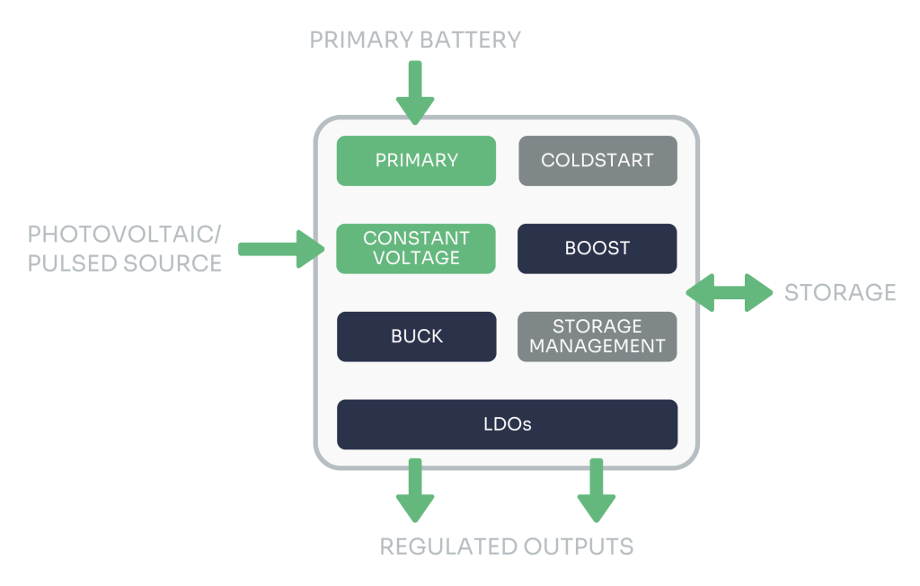
e-peas’ AEM00940/1 is a high-efficiency energy harvesting PMIC that maximizes power extraction from constant voltage PV cells, intermittent and pulsed power sources. It supports high-efficiency conversion and allows for constant voltage MPPT configuration ensuring adaptability to various harvesters.
With ultra-low power cold start, the AEM00940/1 can efficiently operate from minimal available energy. It has fully configurable storage element protection levels and two regulated output voltages that ensure compatibility with various storage element types to simultaneously store energy in a storage element and supply an application circuit.
Additionally, its balancing circuit allows for safely charging a dual-cell supercapacitor, and its configurable primary battery feature provides a backup solution to guarantee continuous operation in any condition.
Product Information
Products

Power converters
- Harvester: Boost Converter
- Load Outputs: Low-Dropout Regulators (LDO)
Low voltage output
- 1.2 V or 1.8 V
- Max. 20 mA
- Buck Used as Input of the LDO for Best Efficiency
- Dynamically Power-Gated by External Control
High voltage output
- 1.8 V to 4.1 V
- Max. 80 mA
- Dynamically Power-Gated by External Control
Harvester input
- Constant Voltage Source Regulation
- 50 mV to 4.5 V
- Max. 110 mA (AEM00940)
- Max. 10 mA (AEM00941)
- Open Circuit Voltage: Max. 5.0 V
- Cold Start: Min. 3 µW / 380 mV
Extra features
- Primary Battery Support with Configurable Overdischarge Voltage
Storage element
- 2.2 V to 4.5 V
- Configurable Protection Levels
- Dual-Cell Supercapacitor Balancing
Package
- QFN28 5x5mm (AEM00940)
- QFN28 4x4mm (AEM00941)
Features and benefits
- Harvest from 50 mV after cold start
- Up to 110 mA (AEM00940) or 10 mA (AEM00941) current extracted from the harvester
- Optimized for constant voltage PV cells, intermittent and pulsed power sources
- Cold start from 3 µW / 380 mV
- Configurable overdischarge, charge ready and overcharge protections to support a wide range of rechargeable storage element types
- Balancing circuit to safely charge a dual-cell supercapacitor
- LDO regulator with Buck converter used as input for best efficiency
- Selectable output voltage to 1.2 V or 1.8 V
- Output current up to 20 mA
- Dynamically power-gated by external control
- Selectable output voltage from 1.8 V to 4.1 V
- Output current up to 80 mA
- Dynamically power-gated by external control
- Automatically switches to the primary battery when needed
- Configurable primary battery overdischarge voltage
- Reduced external component requirements
Block Diagram
Evaluation boards
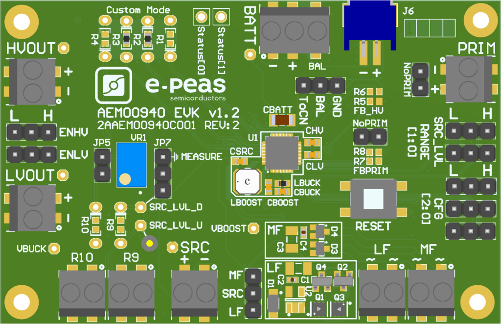
The AEM00940 Evaluation Board (76 mm x 49 mm) offers a complete solution for testing the features and performances of the AEM00940 energy harvesting PMIC in QFN-28 package. It includes the necessary passive components for optimal operation and a set of jumpers for easy configuration.
Designed for flexibility, the board allows full configuration and provides:
- Energy harvester input, with its configuration settings.
- Two Rectifiers, for low and medium frequency AC sources.
- Connection for the storage element, with configurable protection levels, custom mode and balancing feature configuration.
- Two regulated LDO outputs, with voltages and enabling configuration.
- Connection for the primary battery, with minimum voltage and enabling configuration.
- Status signals pin access.
For detailed setup and advanced features, refer to the AEM00940 datasheet and EVK documentation.
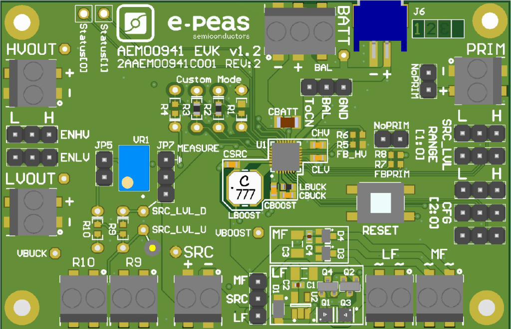
The AEM00941 Evaluation Board (76 mm x 49 mm) offers a complete solution for testing the features and performances of the AEM00941 energy harvesting PMIC in QFN-28 package. It includes the necessary passive components for optimal operation and a set of jumpers for easy configuration.
Designed for flexibility, the board allows full configuration and provides:
- Energy harvester input, with its configuration settings.
- Two Rectifiers, for low and medium frequency AC sources.
- Connection for the storage element, with configurable protection levels, custom mode and balancing feature configuration.
- Two regulated LDO outputs, with voltages and enabling configuration.
- Connection for the primary battery, with minimum voltage and enabling configuration.
- Status signals pin access.
For detailed setup and advanced features, refer to the AEM00941 datasheet and EVK documentation.
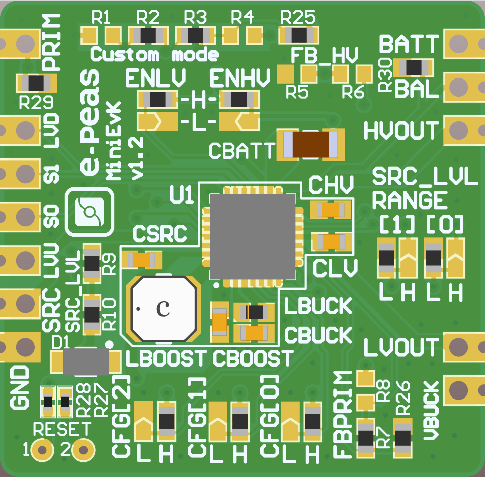
The AEM00940 Mini Evaluation Board (28 mm x 28 mm) offers a compact alternative to the standard evaluation board and supports all the AEM00940 configurations and functionalities while offering easier integration into development setups.
- All connections via solder pads ensure easy access.
- Configurable via solder bridges and resistors, supporting full flexibility in setup.
- Optimized for quick prototyping.
For detailed setup and advanced features, refer to the AEM00940 datasheet and mini EVK documentation.
How it works
Basic Functionality
Energy Harvesting Sources
Load Regulation
STO Protection
DC-DC VS LDO
Support
Need advice on choosing the right solution for your appliances?
We are here to assist you every step of the way. At e-peas, your satisfaction is our priority!
Our products are suitable for a wide range of applications
Smart Home & Buildings
Consumer Electronics
Industrial IoT
Smart Retail
Wearables
They tried it. They signed up for life for their devices.
Our customers share their experiences.

Vice-President Business Development at Nichicon

FAE Director at Epishine

CEO of TEGnology

Senior Vice President of Strategy and Business Development at Energous
Contact us
Ready to test?
Your next technological breakthrough starts here.
You may also be interested
Not so fast!
Discover our wide range of products that are revolutionizing the autonomy of intelligent devices and the sectors we address.
Applications
Our cutting-edge solutions are driving change across sectors – smart home, consumer electronics, industrial IoT and beyond.
Energy harvesting PMIC (AEMs)
Enable your devices to harvest more with our ambient energy managers.
New solution: microcontroller (MCU)
Enable your devices to consume less with our microcontroller EDMS105N.
Need some advice?
Find the ideal solution with our experts.
Any questions?
WHICH AEM (PMIC) – POWER MANAGEMENT INTEGRATED CIRCUIT – DO I NEED FOR MY APPLICATION?
All our AEMs (PMICs) share the same purpose: manage the power from an harvester to a storage and/or a load.
However, their coldstart, MPPT ratio and timing might be different to be adapted to the source they should harvest from. For more details, please see “What is the MPPT ratio?” question.
To choose wisely your PMIC, please keep in mind it must be adapted to your harvester and its behavior.
Explore e-peas’ PMIC Selector Guide for more detailed comparison of PMICs.
HOW TO ANALYZE THE POWER BUDGET OF AN ENERGY HARVESTING SYSTEM?
When working with energy harvesting, the most important step is the power budget analysis.
Indeed, to build a viable system, enought power must be harvested to supply the target application.
Here below, we propose to study the power budget for choicing the adequate elements.
This study is composed of steps to define the parameters useful in the storage and source choice.
Those steps have no real order; and different ways for using them exist.
- On ways is starting from the load consumption to define the source and the storage element size.
- Another way is starting from the source to estimate the available left power for the load and the storage element size.

Please note that below, TS represents the time with available power at the source; and TNS represents the time without power available at the source.

If starting from load consumption :
- STEP EC : Evaluate the energy consumed EC by the load during a repeatable period (a day, a week, a month, …). This period must be chosen to include all TS and TNS time. For example, one day is a typical period for outdoor solar application since light is coming back every day. A week could be adapted for indoor application without light during the week-end.
The formula below includes 2 different active current peak [A1 and A2] and passive current [P]. Units below are A for current, V for voltage and s for the time.
EC = (IA1 x VA1 x TA1 + IA2 x VA2 x TA2 ) + ( IP x VP x TP ) [ J ]
Active consumption is mostly due to radio communication or processing. Passive consumption is the sleep power or any constant consumption required by the load.

- STEP E BOOST : Calculate the energy to be harvested EBOOST in order to supply the load.
The formula below includes converter used between the storage and the load. If using internal LDO converters, their efficiency is provided in the AEM datasheet. For external converter, the efficiency should be given in its datasheet.
Please note that the internal leakage of the storage should be taken into account.
E BOOST = EC / n LDO (or n DCDC) + E leak [ J ]
- STEP E STORE : Calculate the required energy E STORE to be stored. Based on the autonomy and the load consumption, size of the storage must be define.
The formula below implies an autonomy egals to TNS – time with no power available at the source.
E STORE = ( TNS / TNS + TS ) x E BOOST [ J ]
For longer/smaller autonomy, the ratio R must be adapted in order to store the energy consumed during the autonomy defined.
E STORE = R x E BOOST [ J ]
If the autonomy required is 2 days, the ratio R is defined as 2*864000 / (TNS+TS) = 2 days / 1 day = 2
-> See FAQ about storage size : How to estimate the storage element size ?
- STEP P SRC : estimate the P SRC source power required to supply the load. Based on the time with available power at the source, the efficiency on the boost; the required power from the source is calculated.
Please note that, if longer autonomy is required, the additional energy to be stored must be harvested first.
Here below, we will define E BOOST* as the energy to boost for the autonomy required which is egal to E BOOST + E BOOST additional.
This E BOOST additional is defined as E BOOST * Z with Z = add time / (TNS+TS).
If the additional time is one day, E BOOST* = 2 x E BOOST.
P SRC = E BOOST / (TS x n Boost ) [ W ]
For RF system, the efficiency over the RF path must be include in that step to estimate the power to be received.
P RECEIVED = E BOOST / (TS x n RF global)
This n RF global efficiency is provided in the AEM30940 datasheet for the e-peas solution. For custom design (external rectifier with associated matching network), this efficiency must be characterized.
If starting from source power :
In that case, the first is to estimate the available power at the source.
This information is given in the harvester’s datasheet for solar, thermal or vibration harvester.
For RF source, the losses in the air must be evaluated to estimate the received power P RECEIVED based on the emitted power.
P RECEIVED = P EMITTED – Losses air
- STEP E BOOST : Calculate the energy harvested EBOOST from the source.
E BOOST = P RECEIVED x TS x n RF global [ J ]
E BOOST = P SRC x TS x n Boost [ J ]
- STEP EC : Evaluate the available energy for the load based on the energy harvested.
EC = E BOOST x nLDO – Eleak [ J ]
The size of the battery is estimate based on E STORE = E BOOST.
WHAT IS THE MAXIMUM INPUT POWER OF THE AEM?
The maximum input current of the AEM is 110 mA and the maximum input voltage is 5V.
P_max @ input voltage 5 V = 550mW
P_max @ input voltage 3 V = 330 mW
CAN I CHANGE THE LBOOST INDUCTOR?
Yes, but some caracteristics are important for the global perfomances.
Indeed, the AEM boost efficiency depends on the the inductor associated. The one recommanded in the datasheet are the ones showing the best performances. If LBOOST inductor has to be replaced, please choose the one with the lowest Rdc resistor and the highest peak saturation current.
The actual recommanded inductors present a Rdc resistor around 300 mOhm and a saturation current around 600 mA.
We can propose those inductors from Wurth Electronik : 744 040 321 00 and 744 383 361 00.
We also identify those ones but we did not test them :
https://product.tdk.com/info/en/catalog/datasheets/inductor_commercial_power_vls201612hbx-1_en.pdf
https://www.digikey.com/product-detail/en/taiyo-yuden/MDKK2020T100MM/587-4093-1-ND/5035253
http://www.bourns.com/docs/Product-Datasheets/SRN2009T.pdf
Details are provided page 12 in the datasheet.
WHAT IS THE MPPT RATIO?
For any harvester, the power curve goes first up, achieves his maximum power point and goes down with the voltage until reaching the open-circuit voltage – Voc. Looking at this power curve, we can see that a maximum power point exists at a certain voltage called Maximum Power Point Voltage – V MPP. This MPP Voltage is a certain percent of the open-circuit voltage – Voc. This ratio varies depending on the harvester : MPPT ratio = VMPP / Voc.
To resume, it defines the best voltage to work with in order to harvest the maximum power out of the harvester.
- For a PV cell, the ratio varies from 70% to 90% depending on the PV cell material.
- For a piezoelectric generator, the ratio depends on the power curve of the piezo including the rectifier.
- For a thermoelectric generator, the ratio is most of the time around 50%.
- For RF, using the integrated rectifier in the AEM30940, the optimal ratio is around 65%.
- For the RF, using an external rectifier with the AEM30940, the optimal ratio of our design is around 50%.
For any harvester, it might be interesting to draw its power curve in the targeted conditions.
Note that the P-V curve might vary under different luminosity for PV cell for example, but the ratio will remain the same.

The AEM10941 performs a Voc measure each 5 s during 81 ms to adapt the VMPP voltage to work at. The ratio is defined by the SELMPP0-1 pin-configuration (See page 12 in the datasheet).
The AEM20940 performs a Voc measure each 21 s during 330 ms to adapt the VMPP voltage to work at. The ratio is defined by the SELMPP0-1 pin-configuration (See page 12 in the datasheet).
The AEM30940 performs a Voc measure each 0.33 s during 5 ms to adapt the VMPP voltage to work at. The ratio is defined by the SELMPP0-1 pin-configuration (See page 12 in the datasheet).
